THE FIRST TWO WRIST WATCHES FITTED WITH AN UP-AND-DOWN INDICATOR
From time to time new inventions or adaptations of old ideas enliven the horological market. Thus two Swiss firms, Zodiac and Jaefer Le Coultre, have recently constructed the first self-winding wristwatches with an up-and-down indicator. This device is not normally used in horology either because there is no need of it, or because there are technical difficulties in the way. These difficulties frequently baffle the repairer, who only rarely encounters watches of this type.
The first time the author encountered this mechanism was during his stay at the School of Horology at Glashutte, where this device finds considerable favour. A number of precision pocket watches equipped with a most satisfactory up-and-down indicator has been used from time to time on watches, but never to any great extent, one of the best known being Breguet's famous Marie-Antoinette watch. Nowadays it is fitted to marine chronometers and to some pocket watches and dashboard clocks for cars and aeroplanes.
The object of the indicator is to show the state of wind of the mainspring, that is to say, the number of hours the watch can run. It may well be asked whether it is necessary to introduce a complicated piece of mechanism to give such an indication; a person of regular habits winds his watch regularly in the morning or evening, but everyone is not regular.
In the following article a type of watch will be described for which an indicator of this sort is particularly desirable. The torque output of a mainspring is not constant, and this causes variations in the amplitude of oscillation of the balance, which is bound to some extent to influence the rate of the watch. Observations of rate should be made every 24 hours; for watches going more than a thoroughly well constructed watch, and to observe certain conditions regarding its treatment in service. This is particularly important in the case of a marine chronometer, as an error of one second of time when determining the position at sea corresponds to an error of the order of 550 yards. If the voyage lasts a number of days, this error might be cumulative, and the determination of position might become so inaccurate as to cause a shipwreck. Ships generally carry three chronometers; if the rate of one shows a departure it is probable that the other two will not, and the time shown by the two chronometers which have not varied will probably be correct. Thanks to the time signals available today, it is easy to observe the errors of rate of marine chronometers. If the rate of a chronometer is to be studied, it is important to wind it at regular intervals. However, it may well happen on board ship that the same member of the crew does not always wind the chronometers, and it is therefore necessary to have some indication of the state of wind of their mainsprings.
On the dial of a 2-day marine chronometer a small secondary dial will be found below the figure 12, showing the state of wind of the mainspring. It is generally in the form of an arc of a circle subtending about 320 degrees, and it might have a division every eight hours; a hand traverses this dial. When this hand is over the figure 48 the chronometer should be wound, there being 8 hours in reserve in the case of a normal chronometer. The up-and-down hand, unlike the other hands of the chronometer, moves in one sense and during going it moves in the other, and it is never stationary.
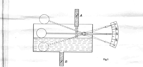
The following analogy will make these two movements clear. Figure 1 shows a vessel containing water, and a float coupled to a pointer. The water enters by the pipe A and leaves by the pipe B. If the vessel is empty the float will lie on the bottom and the pointer will indicate zero. If the value B is closed and the water continues to enter at A the float will rise and the pointer will move towards the full mark. If the water continues to enter the vessel it will overflow, but the float will not rise any more and the pointer will remain stationary on the full mark. When the vessel is only partially full the pointer will take up an intermediate position, and each time the water enters or leaves it will move in one direction or the other. In the case of a watch, the vessel will be seen to represent the mainspring barrel and the pointer the up-and-down hand. The two extreme positions of the hand indicate that the spring is completely wound up, or unwounded to the point at which winding is necessary. In the case of the vessel it has been mentioned that under certain circumstances the water could overflow, and something analogous may occur in self-winding watches, as they may go on winding indefinitely; in this case the mainspring will commence to slip when fully wound.
There are two kinds of up-and-down indicator; in the first the winding arbor revolves in the reverse direction during the going of the watch, in which case the up-and-down mechanism is exceedingly simple. Marine chronometers come into this category, and the up-and-down mechanism consists merely of a pinion mounted on the fusee arbor engaging with a wheel, which carries the up-and-down hand; this wheel turns on a stud. The gear ratio is so chosen that the wheel makes less than one spring. The fusee turns with its arbor during winding, and thus revolves in one sense during going and in the other during winding.
In going barrel watches the problem is much more complicated, and those cannot properly understand except the up-and-down mechanism with some scientific background. In a going barrel remains stationary during winding, which is performed by revolving the barrel arbor; this in its turn is held stationary by the clockwork during going. The problem, therefore, consists in making these two different and independent movements operate the same hand. The most satisfactory solution is that of using differential gears, which is well known in automobile engineering; however few motorists understand the working of this device. Such gearing is called << differential>>, since if two movements are occurring in opposite senses the movement of the third part of the systems is dependent on their difference. Both spur and bevel wheels may be used in differential gearing.
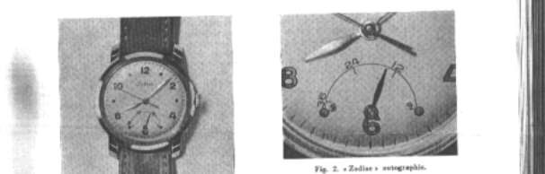
The ZODIAC Autographic
Figure 2 shows a section of the up-and-down mechanism of the Zodiac Autographic; this watch is made as a production item. In the position normally occurred by the small seconds dial will found an arc bearing the figures 0, 12, 24 and 36; these are traversed by the up-and-down hand. When it is over the figure 0 it signifies that the watch is run down and there is no reserve of going. Beyond the figures 0 and 36 two cylindrical screw heads serve as stops for the hand. These stops would serve no useful purpose in a watch of the ordinary type fitted with stop work, but in this case we are dealing with self-winding watches which may continue winding indefinitely, and the up-and-down hand must not pass the figure 36. The stop at 0 is necessary because of backlash in the gearing, and in case of irregular unwinding of the spring.
During winding, either automatically or manually, the hand moves from the figure 0 and traverses the scale towards 36 passing over 12 and 24. If the watch is allowed to run without being moved the hand would retrace its path in the reverse direction. The up-and-down indicator will function continually whatever the position of the hand. Figure 3 shows a section of the mechanism.
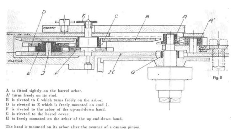
Wheels which move during winding. The 14 toothed pinion A is fitted tightly below the lower pivot of the barrel arbor; it engages with A' which also has 14 teeth and can turn freely on its stud. A' is merely used to reverse the direction of rotation and does not affect the gear ratios. The wheel B has 84 teeth and engages with A'. It is riveted to the pinion C. The pinion C has 14 teeth and can turn freely on the arbor of the up-and-down hand.
The wheel D has 21 teeth and engages with the pinion C.
It is riveted to the pinion E. The pinion E has 15 teeth and is freely mounted on the stud J; it engages with the wheel F. The wheel F has 20 teeth and is riveted to the arbor of the up-and-down hand; this arbor turns freely in the plate and in the up-and-down mechanism bridge.
The operation of the up-and-down indicator.
The 14-tooth pinion G is riveted to the barrel cover. The wheel H has 84 teeth and is freely mounted on the arbor of the up-and-down hand. It carries the stud J that in its turn carries the wheel D and the pinion E. The other wheels in this mechanism are the same as those, which function during the winding. The hand K is mounted friction tight on its arbor after the manner of a cannon pinion. The watch runs for 36 hours and the barrel have 64 teeth and the centre pinion 10 leaves.
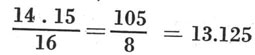
The wheel D and the pinion E that are mounted on the stud J form a most important part of the mechanism; they revolve with the wheel H. The wheel H revolves on its axis in the normal way, and as it does so the planetary wheels D and E revolve with it in engagement with the pinion C. During winding the motion is transmitted through wheels A, A' B, C, D, E and F. The number of revolutions of the up-and-down hand during winding for 36 hour run will be: -


This corresponds to an angle of 169 degrees, and will the hand during winding turn through the angle.
The direction of rotation of the wheels is as follows, clockwise rotation being signified by a plus sign and anti-clockwise by a minus sign. {A-; A'+; B and C-; D and E+; F-} Thus during winding the hand moves in an anticlockwise direction.
Figure 3 shows that winding occurs without affecting the wheel train of the watch in any way. During the going of the watch the wheels G, H, D, E and F are in action, but the directions of rotation are less easy to follow.
The wheels G and A and H and B have the same numbers of teeth, and during going the barrel makes the same number of turns as the barrel arbor makes during winding. Wheels H and B will therefore both make 15/16 turns. The stud J is fixed to the wheel H, and D and E will move with it. These two wheels thus revolve around the stationary pinion C and the freely mounted wheel F. The wheel D and the pinion E thus carry out two movements, but the pinion C is held fixed by the wheel B which is engaged with the pinion A, mounted rididly on the barrel arbor; the barrel arbor is stationary during the going of the watch. When H revolves, the wheel D revolves round C and at the same time rotates on its own axis. The same is true of E, which is riveted to D. The pinion E drives the free wheel F in the normal manner. Up to the wheel H it is possible to calculate the numbers of turns performed in the normal way.
The directions of rotation of the wheels are follows: G-; H+; D and E+; F-
Thus the direction of rotation of F is the same as during winding; but it is required to have rotation in the opposite direction. This might easily be achieved by removing the pinion A'. However, before performing such a modification the matte must be examined forms a different point of view. Imagine that the pinion G on the barrel cover is removed. It would then be possible to revolve the wheel H, the wheel D and the pinion E freely around the stationary pinion C, but E is still in engagement with the wheel F which is mounted on the arbor of the up-and-down hand, and this wheel is not in engagement with any other. The hand can, therefore, follow the movements of E transmitted to it by F.
The movement of the wheels D, E and F is shown in figure 4, in which the letters C, D, E and F have the same significance as before. Thus D and E can turn freely on the stud J and revolve around the pinion C owing to the movement of the wheel H. The point of contact of the pitch circles of C and D will initially be on the line of centres VW. When H turns in the direction of the arrow, D will do likewise, but will also revolve on its own axis. The point X will describe an epicycloidal curve towards Y, since the wheel D rolls around the pitch circle of C; this movement is caused by the engagement of the two wheels. The curve described is not the normal type of epicycloid since the generating circle is, in this case, larger than the stationary circle.
When the wheel H makes one turn 14 teeth of C will have passed by, as C is a 14-toothed pinion. However, H only makes 15/16 of a turn and thus,
 teeth of C will pass by, teeth of C will pass by,
and, therefore, D which is in engagement with C and has 21 teeth will perform,
 5/8 turns. 5/8 turns.
Then the pinion E, which is solid with D, must make the same number of turns; E also engages with F.
Let us examine the movement of E and F, removing the pinion C. Consider that the wheel B and the pinion C are removed, and that the wheel H is revolved. The wheels D, E and F will revolve together. F will make the same number of turns (15/16) as H in the positive sense.
The pinion E and the wheel F will have no movement relative to one another since F and its arbor are free to turn without constraint.
Only the pinion E, with which it engages, moves the wheel F.
Consider that the wheel B and the pinion C are replaced and that H is revolved through 15/16 of a turn, the movement of D and E will be retarded because of the engagement of the wheels C and D which are in the ratio 14/21. The number of turns of D and E will, therefore, be,

Which is the dame number of turns as before.
If F and E had the same number of teeth, the wheel F would also make 5/8 turns in the positive sense. However, the ratio between E and F is 15/20 and, therefore, the movement of F will be slower. F, will, therefore, make 5/8X15/20=15/32 turns.
The movement of the pinion E and the wheel F is retarded by the rolling of E around fin this case the point X’ in 15/16 of a turn of the wheel H does not go as far as Y’ but ends up at Z on the radius VZ.
The curve described by X’ is similar to an ecicycloid foreshortened in the ratio of 15/20. This curve has not been shown on the diagram for the sake of clarity.
The angle of rotation X’ VZ of the wheel F and, therefore, the up-and-down hand is again 169 degrees as it was during winding, but this time it has occurred in the positive direction. To understand that the up-and-down indicator does not interfere with the free movement of the wheel train of the watch, it will be necessary to study the above description several times.
The power absorbed by this mechanism is exceedingly small, as the wheels are well made and the moving parts nicely free on their arbors. The mechanism is easy to assemble in the factory or after repair, and it is impossible to put a wheel be mounted on to its arbor in any position whatever; after winding the hand will automatically take up the correct setting, due to the provision of the stops, and the fact that the hand is friction tight on its arbor.
The mechanism cannot be entirely accommodated within the plates of the watch, and at any rate half of it is mounted above the plate.
This increases the thickness of the movement, but a cleverly designed case and dial have disguised the fact.
*From: Fisher, A., "The First Two Wrist Watches Fitted with an Up-and-Down Indicator, "Journal Suisse d’Horlogerie et de Bijouterie, No. 5-6, 1949, p.157 (Fischer)
|